Package Contents
 |
|---|
| LTU-Rocket |
 |
|---|
| GPS Antenna Mount |
 |
|---|
| External GPS Antenna |
 |
|---|
| Metal Strap |
 |
|---|
| Zip Ties (Qty. 2) |
 |
|---|
| Universal Bracket |
 |
|---|
| IP67 Upgrade Kit (Vent and Gasket) |
 |
|---|
| Gigabit PoE (24V, 1A) with Mounting Bracket |
 |
|---|
| Power Cord |
Antenna Compatibility
The LTU-Rocket is designed for use with the following Ubiquiti® airMAX® Sector antenna models* for Point-to-MultiPoint mode:
- AM-5AC21-60
- AM-5AC22-45
- AM-V5G-Ti
- AM-M-V5G-Ti
- AM-5G16-120
- AM-5G17-90
- AM-5G19-120
- AM-5G20-90
- AP-5AC-90-HD
* Requires Universal Bracket (included).
Installation Requirements
- Clear line of sight between LTU™ AP and stations
- Clear view of the sky for proper GPS operation
- Vertical mounting orientation
- Mounting point:
- At least 1 m below the highest point on the structure
- For tower installations, at least 3 m below the top of the tower
- Ground wires – min. 10 AWG (5 mm2) and max. length: 1 m. As a safety precaution, ground the LTU radio to a grounded mast, pole, tower, or grounding bar.
- Outdoor, shielded Category 6 (or above) cabling and shielded RJ45 connectors are required for all wired Ethernet connections.
- Surge protection should be used for all outdoor installations. We recommend that you use two Ethernet Surge Protectors, model ETH-SP-G2, one near the device and the other at the entry point to the building. The ETH-SP-G2 will absorb power surges and safely discharge them into the ground.
| WARNING: Failure to properly ground your LTU radio will void your warranty. |
|---|

| Note: For guidelines about grounding and lightning protection, follow your local electrical regulatory codes. |
|---|
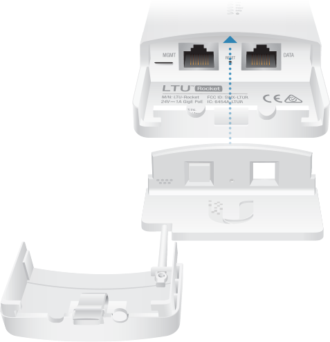
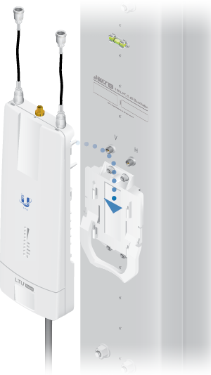
* Shown without antenna.
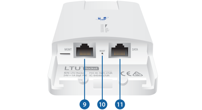
Hardware Overview
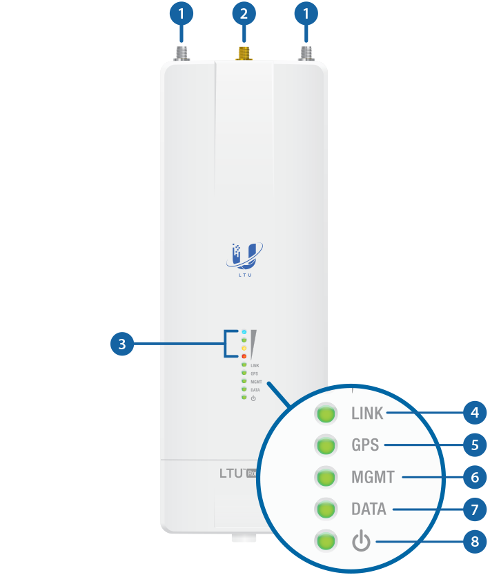

LTU Antenna Connectors |
|
|---|---|
Used to attach RF antenna cables (not included). |
|

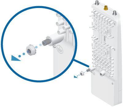
GPS Antenna Connector |
|
Used to attach the GPS Antenna. |
|

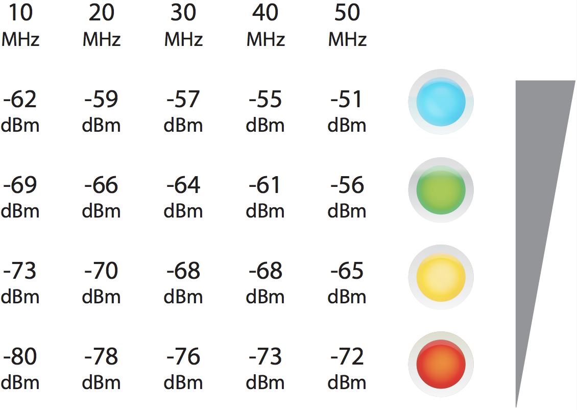
Signal LEDs |
|
Each LED will light when the wireless signal strength is equal to or greater than the LED’s threshold value for the current channel width setting. The default threshold values for each channel width are shown below:
|
|

Link LED |
|
Off |
RF Off |
 |
Syncing |
 |
Beaconing |
 |
Registering |
On |
Operational |

GPS LED |
|
Off |
No GPS Synchronization |
|
Non-Operational (Weak Signal) |
On |
Operational (Strong Signal) |

MGMT LED |
|
LED not used. |
|

Data LED |
|
Off |
No Ethernet Link |
On |
Ethernet Link Established |
Random Flash |
Ethernet Activity |

Power LED |
|
Off |
No Power |
On |
Powered On |
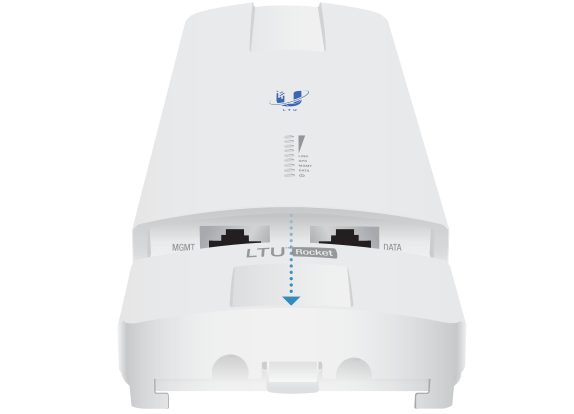
 Management Port |
|
Port not used. |
|
 Reset Button |
|
To reset to factory defaults, press and hold the Reset button for more than 10 seconds while the device is powered on. |
|
 Data Port |
|
Gigabit PoE port for handling all user traffic and powering the device. Default IP address: 192.168.1.20 |
|
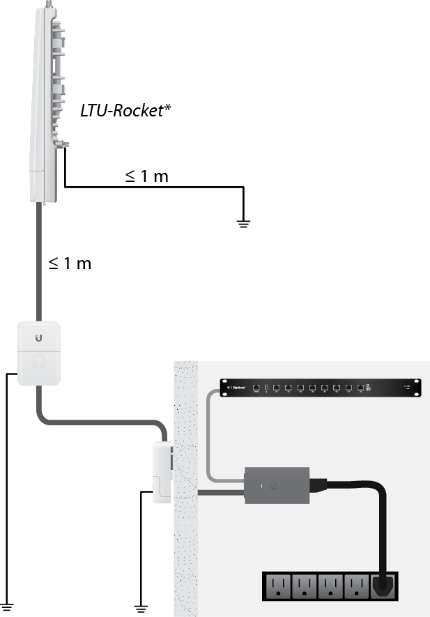
Installation Overview
We recommend that you configure your LTU-Rocket radio before site installation. The following sections provide detailed installation instructions. Perform these instructions in the sequence given.
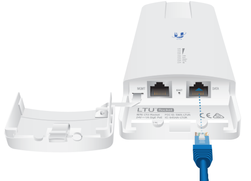
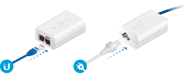
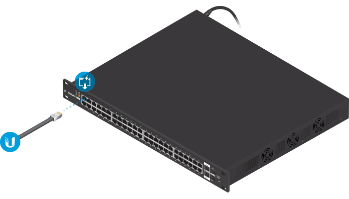
Connecting Power over Ethernet
|
|
WARNING: Use only the included adapter, model POE-24V-5X-HD. Failure to do so can damage the unit and void the product warranty. |
|---|
LTU Configuration
Access the LTU Configuration Interface for configuration. By default, Access Point mode is already enabled for the LTU-Rocket. You can choose to configure settings such as Link Name, Duty Cycle, Channel Bandwidth, and Frequency.
The PTMP stations will scan and find the LTU-Rocket and do not need any frequency set as long as they are set with the same Channel Bandwidth and Link Name.
Configuration Using Browser-Based Interface
- Configure the Ethernet adapter on your computer with a static IP address on the 192.168.1.x subnet.
- Launch your web browser. In the address field, type: http://192.168.1.20
Then press enter (PC) or return (Mac).

- Select your Country and Language. You must agree to the Terms of Use, EULA, and Privacy Policy to use the product. Click Continue.
- Click the
 icon.
icon. - Configure the following settings:
- If needed, change the Channel Bandwidth, Frequency, Output Power (EIRP), Antenna Gain, and Max TX Modulation settings. The Channel Bandwidth should be the same on all devices in the PtMP link.
- In the Security Key field, enter a combination of alphanumeric characters (0-9, A-Z, or a-z).

Note: The key is an alphanumeric password between 8 and 63 characters long.
- Click Save Changes.
- Configure a unique IP address for the Data port:
- Click the
 icon.
icon. - For the Data IP Address option:
- DHCP Have your router use DHCP reservation to assign a unique IP Address.
- Static Change the IP Address, Netmask, and other settings to make them compatible with your network.
- Click Save Changes.
- Click the
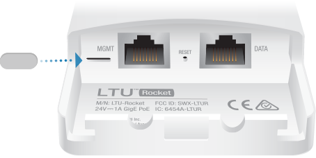
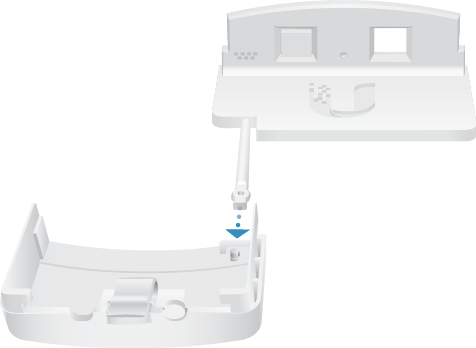
Upgrade for IP67 Compliance
To protect the LTU-Rocket from intrusion by water, dust, and insects, we recommend installing the IP67 Upgrade Kit (included):
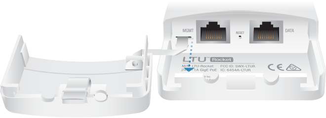
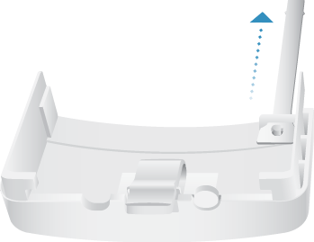
| Note: Do not damage or remove the post on the Port Cover. |
|---|
Hardware Installation
Installing the Ground Wire
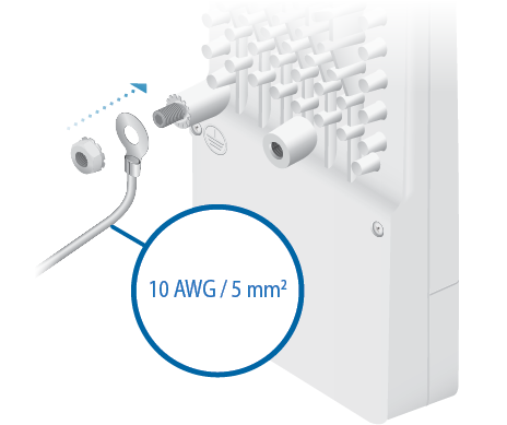
- At the installation site, secure the other end of the ground wire to a grounded mast, pole, tower, or grounding bar.
| WARNING: Failure to properly ground your LTU radio will void your warranty. |
|---|
| Note: The ground wire should be as short as possible and no longer than one meter in length. |
|---|
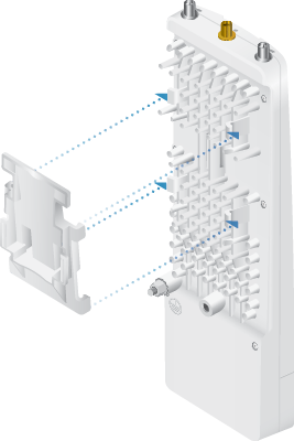
Mount to an airMAX Sector Antenna
The LTU-Rocket is designed to mount directly onto the Ubiquiti antennas listed in “Antenna Compatibility”. The airMAX Sector antenna AM-5AC21-60 is shown in this section:
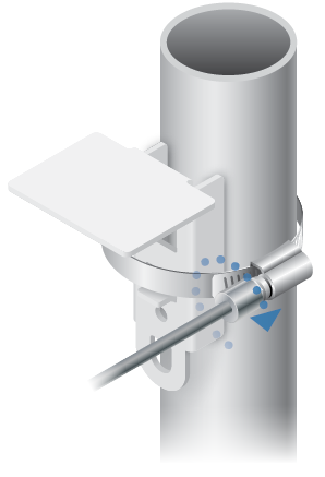
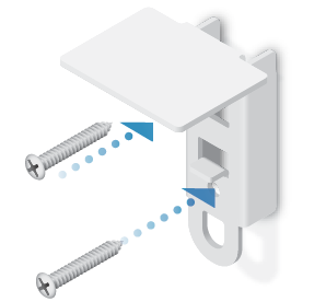
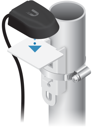
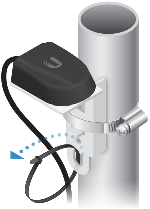
Mount the External GPS Antenna
Locate a mounting point that has a clear view to the sky, and is above and as far away as possible from the LTU-Rocket.
OR
Connecting Power over Ethernet
- 4-pair operation: 18-54V
- 2-pair operation: 30-54V
OR
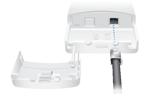
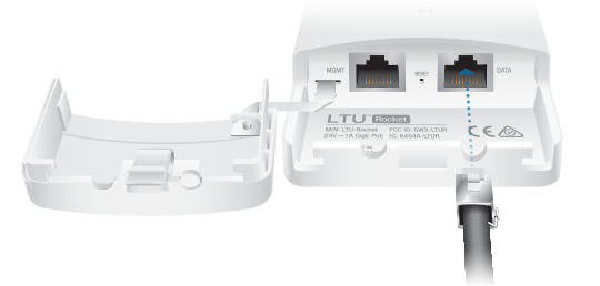
| Note: If the IP67 Upgrade Kit is installed, first apply dielectric grease to the cable connector and port. |
|---|
| WARNING: The LTU-Rocket must receive a minimum of 15W. Ensure that the voltage range of the PoE source is within these limits: |
|---|
OR
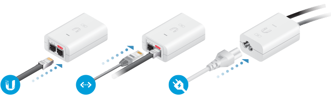
| WARNING: Use only the included adapter, model POE-24V-5X-HD. Failure to do so can damage the unit and void the product warranty. |
|---|
Optional
Installer Compliance Responsibility
Devices must be professionally installed and it is the professional installer’s responsibility to make sure the device is operated within local country regulatory requirements.
Antenna
Select your antenna from the list. If Auto Output Power is enabled, transmit output power is automatically adjusted to comply with the regulations of the applicable country. For a Custom antenna, Antenna Gain is entered manually. Note the requirements and antenna types listed below.
Cable Loss (When applicable)
Enter the cable loss in dB. Output power is adjusted to compensate for loss between the radio and the antenna.
Certified Antenna Types
This radio transmitter FCC ID: SWX-LTUR / IC: 6545A-LTUR has been approved by FCC / ISED Canada to operate with the antenna types listed below with the maximum permissible gain for each antenna type indicated. Antenna types not included in this list or having a gain greater than the maximum gain indicated for that type, are strictly prohibited for use with this device.
|
Antenna |
Frequency |
Gain |
|---|---|---|
|
Sector |
5 GHz |
22 dBi |
Specifications
|
LTU-Rocket |
|
|
Dimensions |
244 x 82 x 48 mm (9.61 x 3.23 x 1.89") |
|---|---|
|
Weight |
0.468 kg (1.03 lb) |
|
RF Connectors |
(2) RP-SMA Weatherproof (CH0, CH1) (1) SMA Weatherproof (GPS) |
|
GPS Antenna |
External, Magnetic Base |
|
Power Supply |
24VDC, 1A Gigabit, 4-Pair Passive PoE (Included) |
|
Power Method |
Proprietary Passive PoE |
|
Supported Voltage Range |
+18 to +54VDC1 |
|
Max. Power Consumption |
15W |
|
Networking Interface |
|
| Data Port | (1) 10/100/1000 Ethernet Port Bluetooth v4.0 |
| Management Port | (1) 10/100/1000 Ethernet Port (Reserved for Future Use) |
|
Mounting |
Integrated Pole Mount (Included) Rocket Mount Compatible GPS Pole Mount (Included) |
|
Operating Temperature |
-40 to 55° C (-40 to 131° F) |
|
Weatherproofing |
IP672 |
|
Certifications |
FCC Part 15.407 |
1 Full range depends on Ethernet cable length.
2 After installation of IP67 Upgrade Kit (included).
|
System |
|
|
Maximum Throughput |
|
|---|---|
| 50 MHz Capacity | 675.84 Mbps1 |
|
Maximum Range |
100+ km |
|
Packets per Second |
2,000,000 |
|
Encryption |
WPA2-PSK (AES) |
|
Forward Error Correction |
LDPC |
|
Uplink/Downlink Ratio |
25/75, 33/67, 50/50 |
|
OS |
airOS LTU |
|
Wireless Modes |
AP |
|
Radio |
|
|
Max. Conducted TX Power |
23 dBm2 |
|---|---|
|
Frequency Accuracy |
< 2 ppm |
|
Channel Bandwidth |
10/20/30/40/50 MHz Selectable |
|
Operating Frequency (MHz) |
||
|
Worldwide |
4800 - 62002 |
|
|---|---|---|
|
US/CA |
U-NII-1 | 5150 - 5250 |
|
U-NII-2A | 5250 - 5350 |
|
|
U-NII-2C | 5470 - 5725 |
|
|
U-NII-3 | 5725 - 5850 |
|
1 May vary depending on environmental conditions.
2 Depends on regulatory region.
|
Bluetooth LE Management Radio (MHz) |
|
|
Worldwide |
2400 - 2483.5 |
|---|---|