Package Contents
The following components will be required for:
- HDD Installation: Components D or E
- Rack Mounting: Components A, B, C, and F
- Flat Surface Staging: Component G
 |
|---|
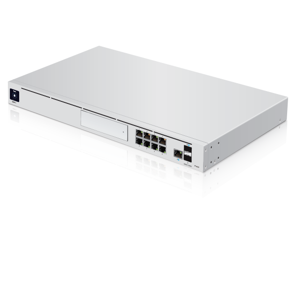
| UniFi Dream Machine Pro |
 |
|---|
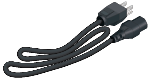
| Power Cord |
 |
|---|
| A- Bracket Screws (Qty. 8) |
 |
|---|
| B- Mounting Screws (Qty. 4) |
 |
|---|
| C- Nuts (Qty. 4) |
 |
|---|
| D- Security Screw |
 |
|---|
| E- 2.5" HDD Screws (Qty. 4) |
 |
|---|
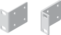
| F- Rack-Mount Brackets (Qty. 2) |
 |
|---|
| G- Rubber Feet (Qty. 4) |
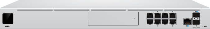
Hardware Overview
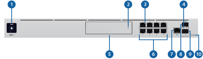


Touchscreen Display |
|
|---|---|
Bootup Animation |
A display message of "UDM-Pro is Starting..." |
Location Animation |
This indicates that you clicked Locate in the UniFi Network Application. The software will also display the location of the device on the map. |

HDD LED |
|
Flashing White |
Indicates Read/Write Activity |
Steady Amber |
Indicates HDD Error |

RJ-45 Speed/Link/Activity LED (Ports 1 - 9) |
|
Off |
No Link |
Amber |
Link Established at 10/100 Mbps Flashing Indicates Activity |
Green |
Link Established at 1 Gbps Flashing Indicates Activity |

SFP+ Speed/Link/Activity LED (Ports 10 - 11) |
|
Off |
No Link |
Green |
Link Established at 1 Gbps Flashing Indicates Activity |
White |
Link Established at 10 Gbps Flashing Indicates Activity |

HDD Bay |
|
Install a 3.5" or 2.5" HDD (not included) to use the device as an NVR for UniFi Protect. |
|

RJ45 LAN (Ports 1 - 8) |
|
The RJ45 ports support 10/100/1000 Ethernet connections. By default, they are set to DHCP Server with the fallback IP address, 192.168.1.1/24. |
|

RJ45 Internet (Port 9) |
|
The RJ45 port supports a 10/100/1000 Ethernet connection. Set to DHCP Client by default. |
|

SFP+ Internet (Port 10) |
|
The SFP+ port supports a 1/10G Ethernet connection. Set to DHCP Client by default. |
|

SFP+ LAN (Port 11) |
|
The SFP+ port supports a 1/10G Ethernet connection. By default, it is set to DHCP Server with the fallback IP address, 192.168.1.1/24. |
|

Reset Button |
|
Resets to factory defaults. The device should be running after bootup is complete. Press and hold the Reset button for about 10 seconds until the display indicates that the device has reset itself. After a few seconds, the LED will turn off, and the device will automatically reboot. |
|

USP RPS LED |
|
Reserved for future use. |
|

USP Connect DC Input |
|
Reserved for future use. |
|

Power Port |
|
Connect the included Power Cord to the Power port. |
|
Hard Disk Drive (HDD) Installation
-
Ensure that your UDM-Pro is fully powered down and unplugged prior to installing your 2.5" or 3.5" HDD.
-
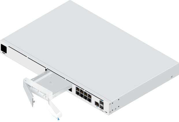
Press the right end of the HDD bay cover inward to unlatch it, then pull the plastic tab out to release the HDD mounting tray.
-
Insert your 3.5" HDD into the mounting tray:

Note: If you are installing a 2.5" HDD,
proceed to Step 4.-
Position your 3.5" HDD inside the mounting tray so that the device's side threading hole is aligned with that of the tray.
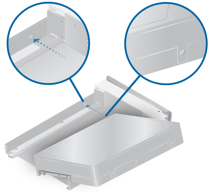
-
Fasten the security screw (D) into the aligned threading hole with a Phillips screwdriver until secure.
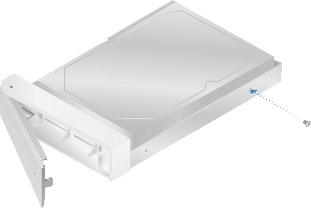
Proceed to Step 5.
-
-
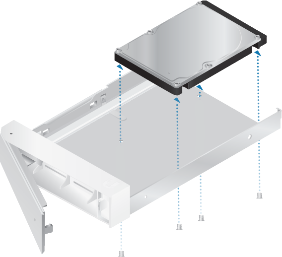
Insert your 2.5" HDD into the mounting tray:
-
Position your 2.5" HDD inside the mounting tray so that the device's threading holes are aligned with those at the bottom of the tray.
Fasten the mounting screws (D) into the aligned threading holes with a Phillips screwdriver until secure.
-
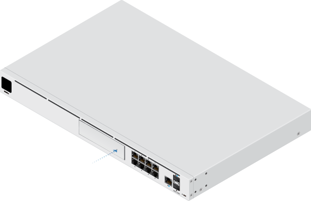
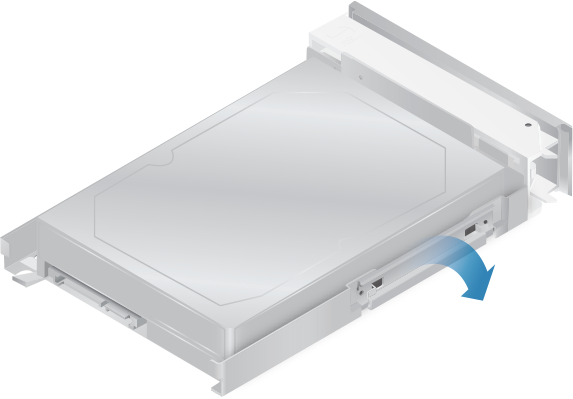
-
Reinsert the tray back into the HDD bay, then push the right end of the bay's front panel in until it clicks into place.
HDD Removal:
-
Ensure that your UDM-Pro is fully powered down and unplugged prior to removing your HDD.
-
Open your UDM-Pro's front panel and pull out the HDD mounting tray.
-
Remove all screws attaching the HDD's chassis to the tray, then remove the device.
-
Reinsert the tray into HDD bay and close the front panel tab.
Rack Mounting the UDM-Pro
Installation Requirements
- Phillips screwdriver
- Standard-sized, 19" wide rack with a minimum of 1U height available
- For indoor applications, use Category 5 (or above) UTP cabling approved for indoor use.
- For outdoor applications, shielded Category 5 (or above) cabling should be used for all wired Ethernet connections and should be grounded through the AC ground of the power supply.
| Note: Although the cabling can be located outdoors, the UDM-Pro itself should be housed inside a protective enclosure. |
|---|
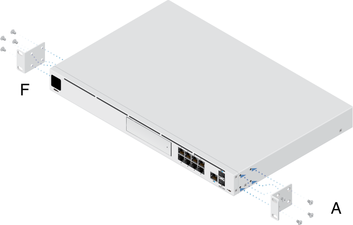
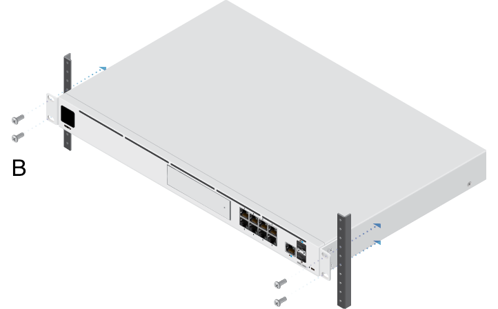
-
Position the first rack-mount bracket (F) so that its four holes align with the four threading holes on either side of the UDM-Pro.
-
Fasten the first rack-mount bracket using four bracket screws (A), then repeat the process with the second rack-mount bracket.
-
Align the front-facing holes of the rack-mount brackets with those of the wide rack's support legs.
-
If your mounting rack's holes are circular, fasten two mounting screws (B) through the rack-mount bracket and the rack's support legs.
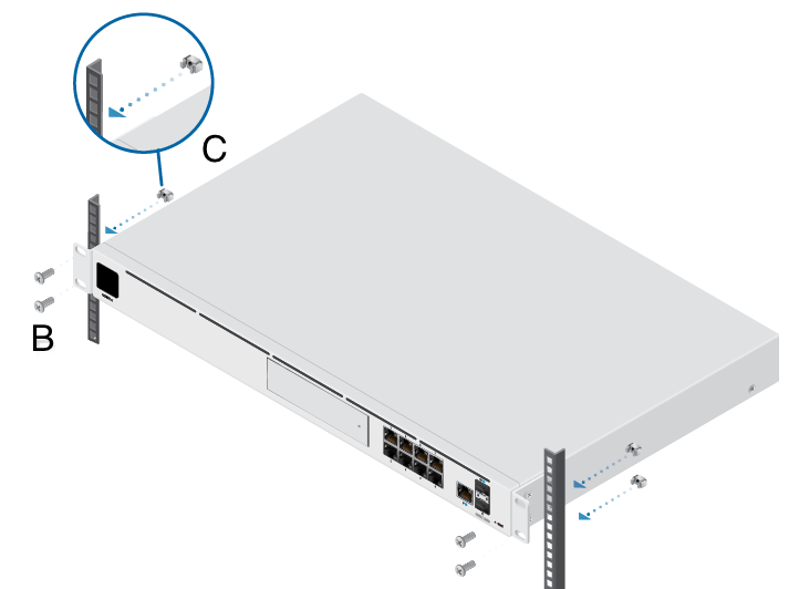
-
If your mounting rack's holes are rectangular:
- Fasten two cage nuts (C) to each of the mounting rack's support legs.
- Thread the mounting screws (B) through the rack-mount brackets and the circular ends of the cage nuts.
-
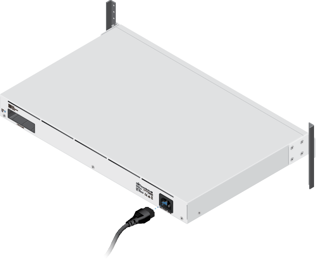
Powering the UDM-Pro
IMPORTANT! We strongly recommend connecting the UDM-Pro to an Uninterruptible Power Supply (UPS), or battery backup device, to prevent power instability issues and hardware damage that may result from relying on the local AC power of a standard outlet.
-
Insert the power cord into the back of the UDM-Pro.
-
Connect the power cord to a standard AC outlet, surge-protected power strip, or a UPS device.
| Note: The UDM-Pro's voltage output range is 100-240 volts. Ensure that your power source can accommodate this, as well as any other devices sharing the UDM-Pro's power supply. |
|---|
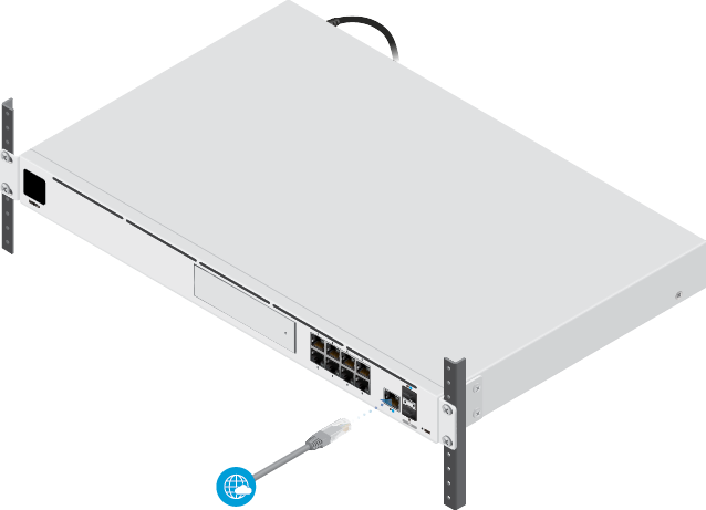
Connecting the UDM-Pro to Your Internet Modem or Router
-
Connect one end of your Ethernet cable to your modem or router, then connect the other end to the RJ45 Internet port on the front of the UDM-Pro (Port 9 in the Hardware Overview table).
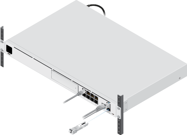
Connecting the UDM-Pro with a Fiber Internet Adapter
-
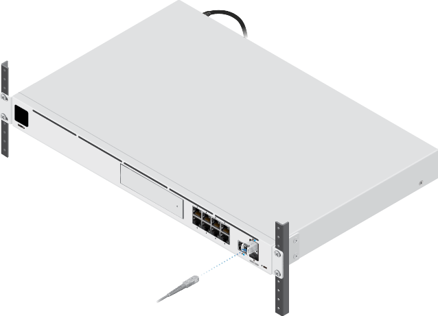
Connect one end of your fiber optic cable to your modem or router.
-
Remove the rubber plug from the SFP+ Internet port (Port 10 in the Hardware Overview table).
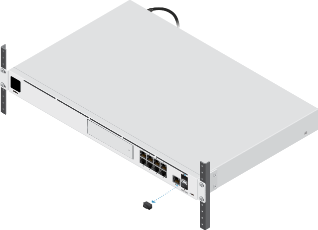
-
Insert your SFP Fiber Module (or compatible third-party equivalent) into Port 10.
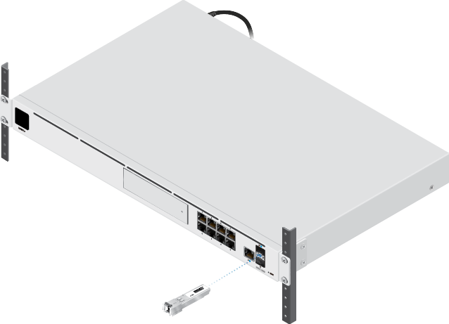
-
Connect the other end of your fiber optic cable to the SFP Fiber Module.
| Note: For more information about compatible fiber SFP modules, refer to our |
|---|
Connecting Devices to the UDM-Pro via LAN Cable
| Note: A LAN, or Local Area Network, connection will directly connect, or "hard line," an individual device (e.g., laptop, game console, etc.) to your UDM-Pro via a separate Ethernet cable. The advantage of this wired configuration is often stronger, steadier download and upload speeds. |
|---|
-
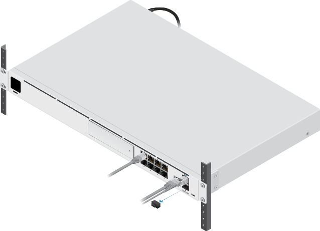
Connect one end of your Ethernet cable to the desired device.
-
Connect the other end of your Ethernet cable into one of the eight RJ-45 ports (Ports 1-8 in the Hardware Overview table).
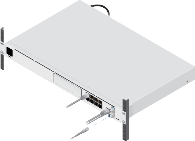
Connecting Devices to the UDM-Pro via Fiber LAN Adapter
-
Connect one end of your fiber optic cable to the desired device.
-
Remove the rubber plug from the SFP+ LAN port (Port 11 in the Hardware Overview table).
-
Insert your SFP Fiber Module (or compatible third-party equivalent) into Port 11.
-
Connect the other end of your fiber optic cable to the SFP Fiber Module.
| Note: For more information about compatible fiber SFP modules, refer to our Help Center article. |
|---|
Configuring and Connecting Devices to the UDM-Pro
To finish setting up your UDM-Pro, please read UniFi - Set Up a Dream Machine Pro.
This guide will take you through the process of configuring your UDM-Pro and connecting all of your UniFi devices. Please check the system requirements below before proceeding to the guide.
System Requirements
Either of the following is required:
- An iOS or Android™ mobile device with the UniFi Network Mobile app installed.
- The Google Chrome web browser.
Note: Other browsers may offer limited functionality.
Specifications
|
UDM-Pro |
|
|
Dimensions |
442.4 x 43.7 x 285.6 mm (17.42 x 1.72 x 11.24") |
|---|---|
|
Weight |
3.90 kg (8.60 lb) |
| With Mount Brackets | 3.99 kg (8.80 lb) |
|
Interfaces |
|
| Networking | (8) 10/100/1000 RJ45 LAN Ports (1) 10/100/1000 RJ45 WAN Ports (1) 1/10G SFP+ LAN Port (1) 1/10G SFP+ WAN Port |
| Management | Ethernet In-Band (1) Bluetooth BLE |
|
Max. Power Consumption |
33W |
|
Power Method |
(1) Universal AC Input, 100 to 240VAC (1) RPS DC Input |
|
Power Supply |
Internal 50W/12V |
|
Supported Voltage Range |
100 - 240VAC |
|
Display |
1.3" Color Touch Panel |
|
LED |
|
| System | Status |
| HDD | Activity |
| RJ45 | Link/Speed/Activity |
| SFP+ | Link/Speed/Activity |
|
Processor |
Quad ARM Cortex-A57 Core at 1.7 GHz |
|
System Memory |
4 GB DDR4 |
|
On-Board Flash Storage |
16 GB eMMC |
|
Operating Temperature |
-10 to 40° C (14 to 104° F) |
|
Operating Humidity |
5 to 95% Noncondensing |
|
Certifications |
CE, FCC, IC |