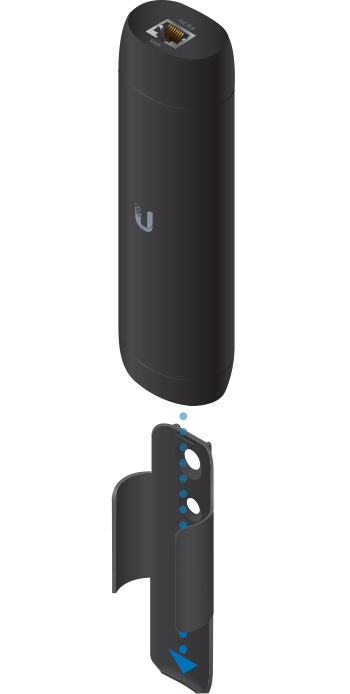
Package Contents
 |
|---|
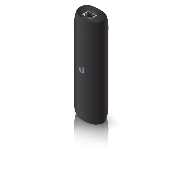
| UniFi Protect ViewPort |
 |
|---|
| Mounting Bracket |
 |
|---|
| Double-Sided Tape |
 |
|---|
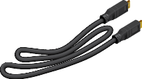
| HDMI Cable |
 |
|---|
| M6 Screw |
 |
|---|
| M8 Screw |
 |
|---|
| Drywall Screws (Qty. 2) |
 |
|---|
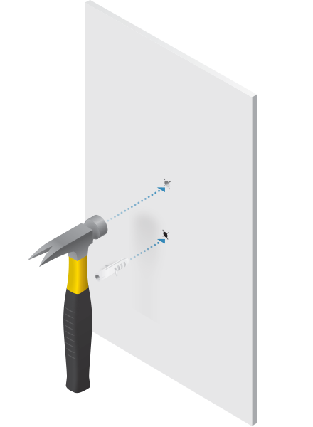
| Screw Anchors (Qty. 2) |
System Requirements
- UniFi Protect Application v1.13 or above, available at ui.com/downloads/unifi
Installation Requirements
- Phillips screwdriver
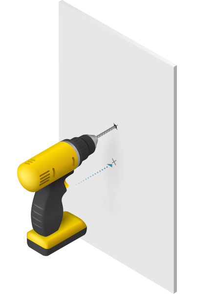
- Drill and 6 mm (1/4") bit for drywall anchors
- Drill and 6 mm (1/4") bit or 8 mm bit (5/16") for screws
- Shielded Category 5 (or above) cabling with drain wire should be used for all wired Ethernet connections and should be grounded through the AC ground of the PoE.
Hardware Overview
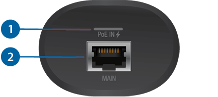

Power/Status LED |
|
|---|---|
Solid White |
Ready for configuration. |
Blue |
The device has been adopted by the UniFi Protect Application. |
Alternating Blue/White |
The device is booting up. |

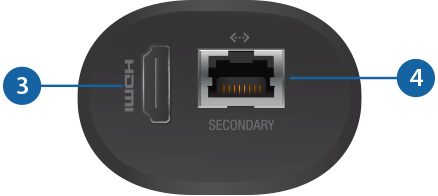
Main Port |
|
This 10/100/1000 RJ45 port connects to an 802.3af switch for PoE power and data. |
|

HDMI Port |
|
This HDMI port connects to a TV or monitor with an HDMI cable. It supports 1080p and 4K displays. |
|

Secondary Port |
|
This 10/100/1000 RJ45 port functions as a data passthrough port. |
|

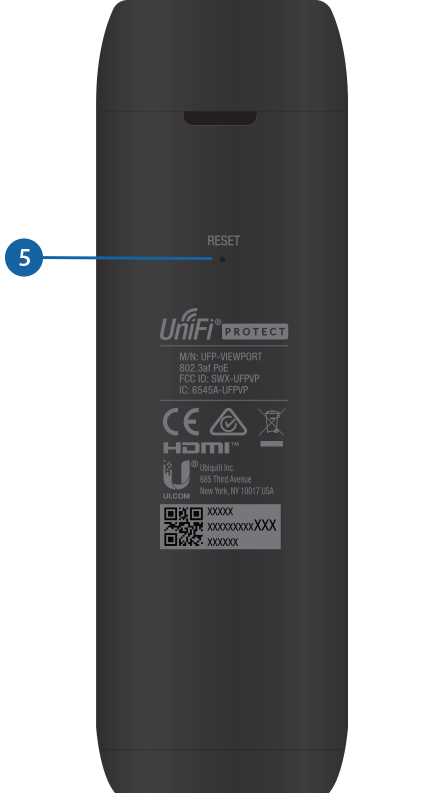
Reset Button |
|
Restore to Factory Defaults Press and hold the Reset button for 5 seconds while the device is powered on. Release the Reset button when the LED turns off. |
|
Hardware Installation
Mounting the UniFi Protect ViewPort is optional; it allows the device to be installed in an inconspicuous and safe location. You have three options for mounting:
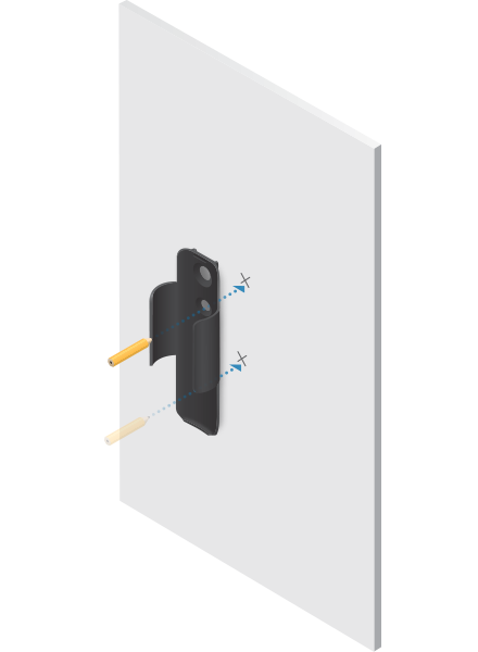
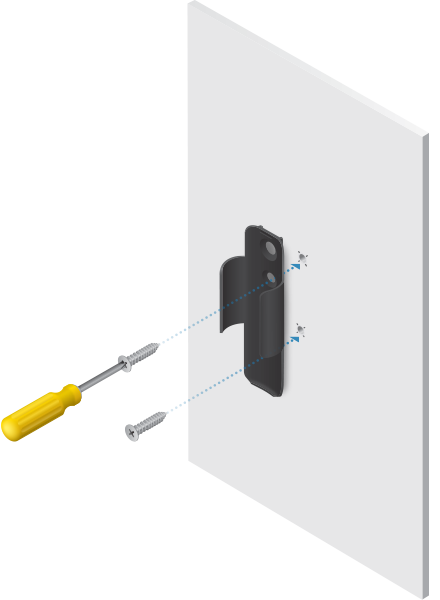
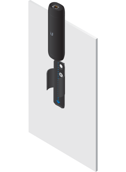
- Wall Mount Mount the ViewPort onto a drywall surface.
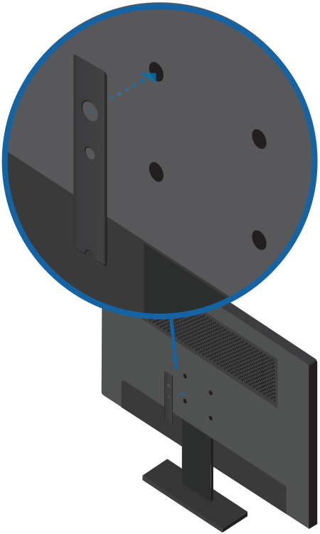
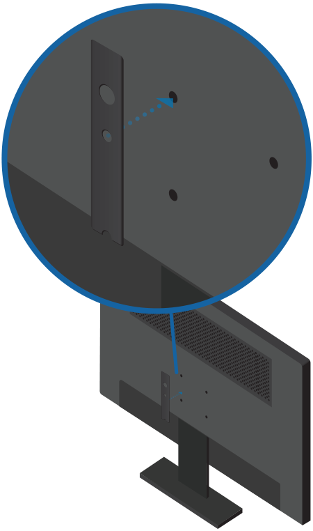
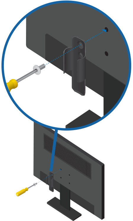
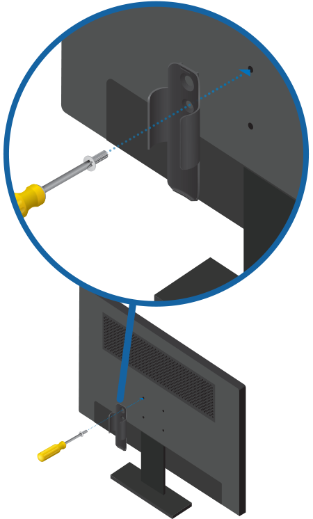
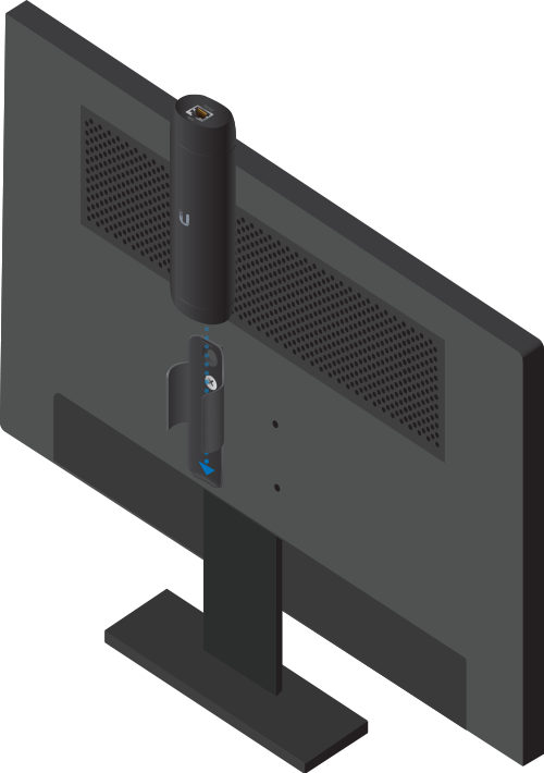
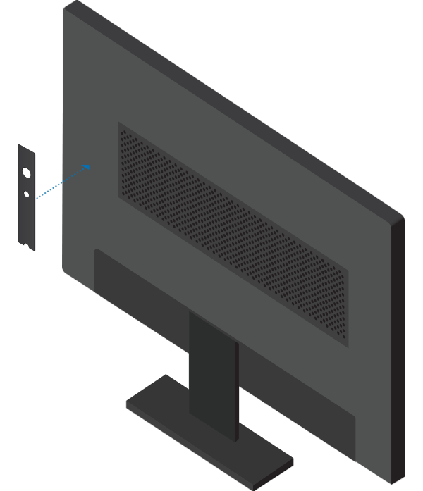
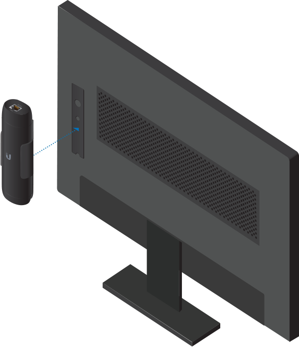
- TV VESA Mount Mount the ViewPort to the back of your TV/monitor using the available VESA mounting hole(s).
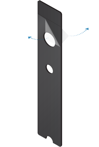
- TV Surface Mount Attach the ViewPort to the TV/monitor or other surface using the included double-sided tape.
Wall Mount
TV VESA Mount
You can use this option if your TV or monitor is equipped with a VESA mount that uses M6 or M8 screws.
Optional
(for permanent mounting)
| OR |
|
M8 Screw | M6 Screw |
| OR |
|
M8 Screw | M6 Screw |
TV Surface Mount
Connecting the ViewPort
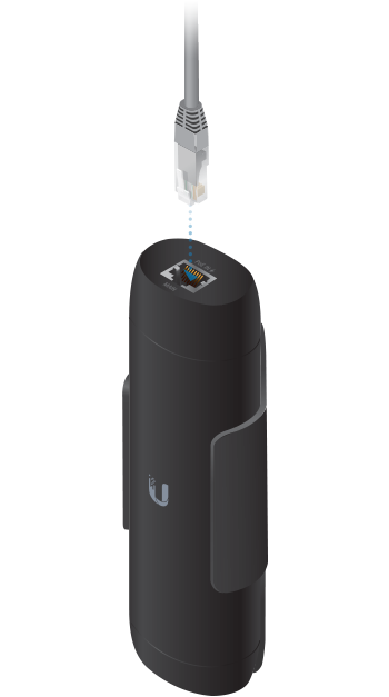
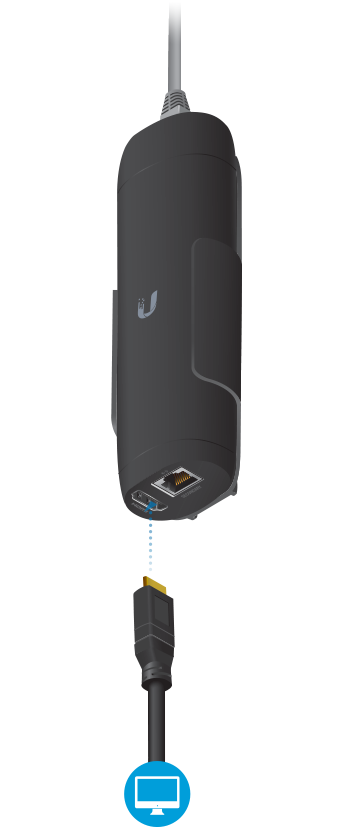
- Follow the instructions on the TV or monitor. (If nothing is displayed, check the power source to the device.)
- Log in to UniFi Protect. Enter the UniFi Protect username and password. Then click Submit.
- When UniFi Protect detects the ViewPort, click Add Device.
| WARNING: The switch port must comply with the power specifications listed in “Specifications”. |
|---|
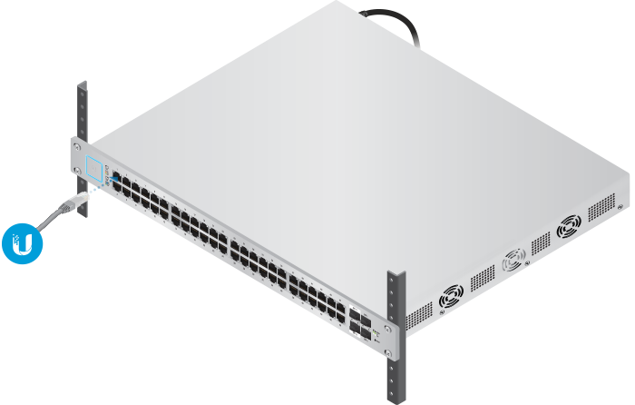
| Note: The PoE switch must be connected to the same LAN or VLAN as the UniFi Protect Application. |
|---|
Specifications
|
UFP-VIEWPORT |
|
|
Dimensions (With TV Mount) |
156.9 x 52 x 37.35 mm (6.18 x 2.0 x 1.47") |
|---|---|
|
Weight |
|
| Without TV Mount | 230 g (8.11oz) |
| With TV Mount | 252 g (8.89 oz) |
|
Enclosure |
Polycarbonate |
|
Networking Interface |
10/100/1000 Ethernet Port |
|
Management Interface |
UniFi Protect Application |
|
Max. Power Consumption |
9.5W |
|
Power Method |
802.3af PoE |
|
Button |
Reset/Factory Reset |
|
LED |
Power/Status |
|
ESD/EMP Protection |
Air: ± 8kV, Contact: ± 4kV |
|
Operating Temperature |
0 to 40° C (32 to 104° F) |
|
Operating Humidity |
20 to 80% Noncondensing |
|
Certifications |
CE, FCC, IC |
